On Thu, 03 Jul 2008 18:33:53 -0700, you wrote:
>1) If there is no load at all on the power supply, I can read +5v on my
>DMM. As soon as there is any load, the regulator shuts down and the LED
>lights up.
>2) The +12v supply is good
Silly question, perhaps, but -- how do you *know* the +12V rail is
good? Have you tested it under load? Also, does it *stay* good even when
the +5V rail goes into shutdown?
>3) The following components have been replaced; The 3525a regulator at U1,
>the LM339 comparator, and the two Mosfet Transistors
Step 1: Check the small-signal diodes at CR3-CR6, CR8, and CR9. Also
check Q4, Q5, and (less likely) Q3 -- or just replace 'em all; they're
dirt-cheap anyway. :)
Step 2: Any electrolytic capacitor on the board is also suspect, just
on general principles.
Step 3: If the above options fail, inspect the resistors in that
comparator circuit closely; make sure none of them have overheated and
opened up or changed value.
Step 4: Consider saving yourself a lot of aggravation and installing a
modern switcher instead. :D
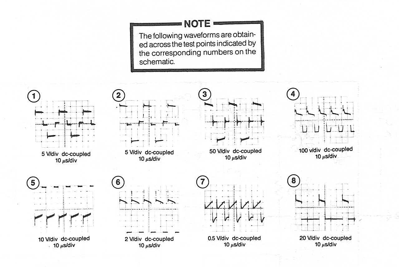
>1) I'm not seeing pulses on pins 11 and 14 of U1 - which are supposed to
>power the T2 Transformer. http://games.rossiters.com/manuals/pulses.jpg
>(Diagram 1)
>On U1 - Pins 5 and 7 I'm seeing a sawtooth wave form, but on pin 6 I'm only
>getting a flat 5volts. The manual says "Resistor R7 and Capacitor C10 set
>the frequency of the U1 oscillator while R8 and C10 set the dead time."
>Should I be seeing some sort of wave form on pin 6?
I don't *think* so, no... unfortunately, the data sheets for the 3525A
are a bit vague on the details, to put it mildly. :(
Scope that Shutdown signal on pin 10. The 3525A is a cranky bastard at
the best of times; *any* high-going noise pulses on that line will cause an
immediate shutdown of the A and B outputs.
>2) I'm assuming I'm supposed to measure the test points with an
>oscilloscope the same way I usually do right? (i.e. Ground lead goes to
>ground, other lead goes to test point). I'm not getting any reading from
>those test point.
Mostly true, but do *NOT* attempt to scope Q1, Q2, the secondary
winding of T2, or the other associated components in that vicinity unless
you have everything connected up to an isolation transformer. Those
components are on the "hot" side, with a potential path right back to the
mains, and that's a good way to generate a lot of sparks. :)
---------------------------------------------------------------------------
** Unsubscribe, subscribe, or view the archives at http://www.vectorlist.org
** Please direct other questions, comments, or problems to chris@westnet.com
Received on Fri Jul 4 00:47:08 2008
This archive was generated by hypermail 2.1.8 : Mon Jul 07 2008 - 18:50:00 EDT