Jess Askey wrote:
> Hi Everyone...
>
> My Amplifone raster saga continues, I now have two deflection boards
> and an original deflection coil (thanks John!) but nothing is working
> yet. Im probably going to go into a little too much info here, but I
> figure more is *more*. :-)
>
> First Important Note: Im running this deflection PBC off the Atari
> switching power supply which puts out 145VDC for the monitor. Oddly,
> this is fed directly in where the 125VAC goes, which if you do the
> analysis, is just fine... it is actually a little easier on the
> monitor power regulator (120V) since it only has to regulate down from
> 145VDC rather than 170VDC. The reason this is important is that the
> switcher shuts down in an overloaded condition (saving me fuses and
> more) any time I power up the monitor. When I first was
> troubleshooting this monitor I had a few times where I doubted that
> the deflection PCB was the problem so I put it on the regular 120VAC
> line... well, that proved one important thing twice (yes, I was
> stubborn enough to learn this the hard way twice). I shorted the HOT
> and the power regulator. So, lets just say that Im pretty sure that
> using the Atari switching power supply is working well as a
> troubleshooting method. As another note, the raster deflection PCB has
> a 1A slow blow fuse in it. I measured the current in my 1 second
> power-up and as best I can see, it peaks at around 1.1A before the
> switcher turns off.
>
> The Current (not amperage) Situation:
>
> When I power up the game, the switcher ramps up and then goes into
> overload in about 1 second. Not much troubleshooting that I can do in
> that one second. If I disconnect the monitor, game comes up fine, just
> blind.
>
> All of this points to the Raster Flyback (Red just like the vector HV,
> different windings tho) being the most obvious problem. However, There
> are some more variables. I have another deflection PCB so I have
> complete comparison to work with. Both deflection PCB's are doing the
> same as described above. I have verified the following on both...
>
> 1. There are no shorts across windings on either flyback
> 2. the DC resistance of both flyback windings are the same(but
> fairly useless since they are so close to 0 ohms)
> 3. The HV diode is not shorted in either flyback
> 4. None of my secondary rectifier diodes are shorted... they all
> test good.
> 5. Both deflection PCB's have been recapped
> 6. Both deflection PCB's have good HOTs
> 7. Both deflection PCB's have good HOT protection diodes (cross
> swapped and also used a spare 3rd diode)
> 8. There are no longer any cold solder joints.
> 9. There are no physical oddities such as cracks or shorts on
> either PCB
>
> In a sad footnote, the second deflection PCB actually worked just fine
> for about 30 minutes before the switcher started shutting down.
>
> So, with all this... again... sounds like the flybacks are both bad
> since those are such likely culprits... I don't have a ring tester,
> but I have more evidence that they are somewhat healthy...
>
> Second Important Note:
>
> The Amplifone raster has an interesting design flaw that is pretty
> nice. When the base of the power regulator (a TO-3, hfe=40 standard
> NPN power transistor) is left floating, the output of the power
> regulator drops down to a solid regulated 36VDC rather than the proper
> 120VDC (30%). This is sort of like having a built in variac around but
> I can still run on the switching power supply as protection. This
> gives me an interesting result... I can actually let the deflection
> PCB run and the switcher does not turn off due to overload,
> additionally, the Horizontal Oscillator runs quite nice.... I have had
> it running while troubleshooting for periods up to 30 minutes at a
> time so it is quite stable too. This allows me to get out the O-scope
> and dig deeper...
>
> First Reference: LOPT Testing Summary -
> http://www.scribd.com/doc/40027645/Flyback-Tester which is short and
> sweet, Sam Goldwassers LOPT FAQ is much more robust but makes the same
> points on explaining they theory of flybacks and how to ring test them.
>
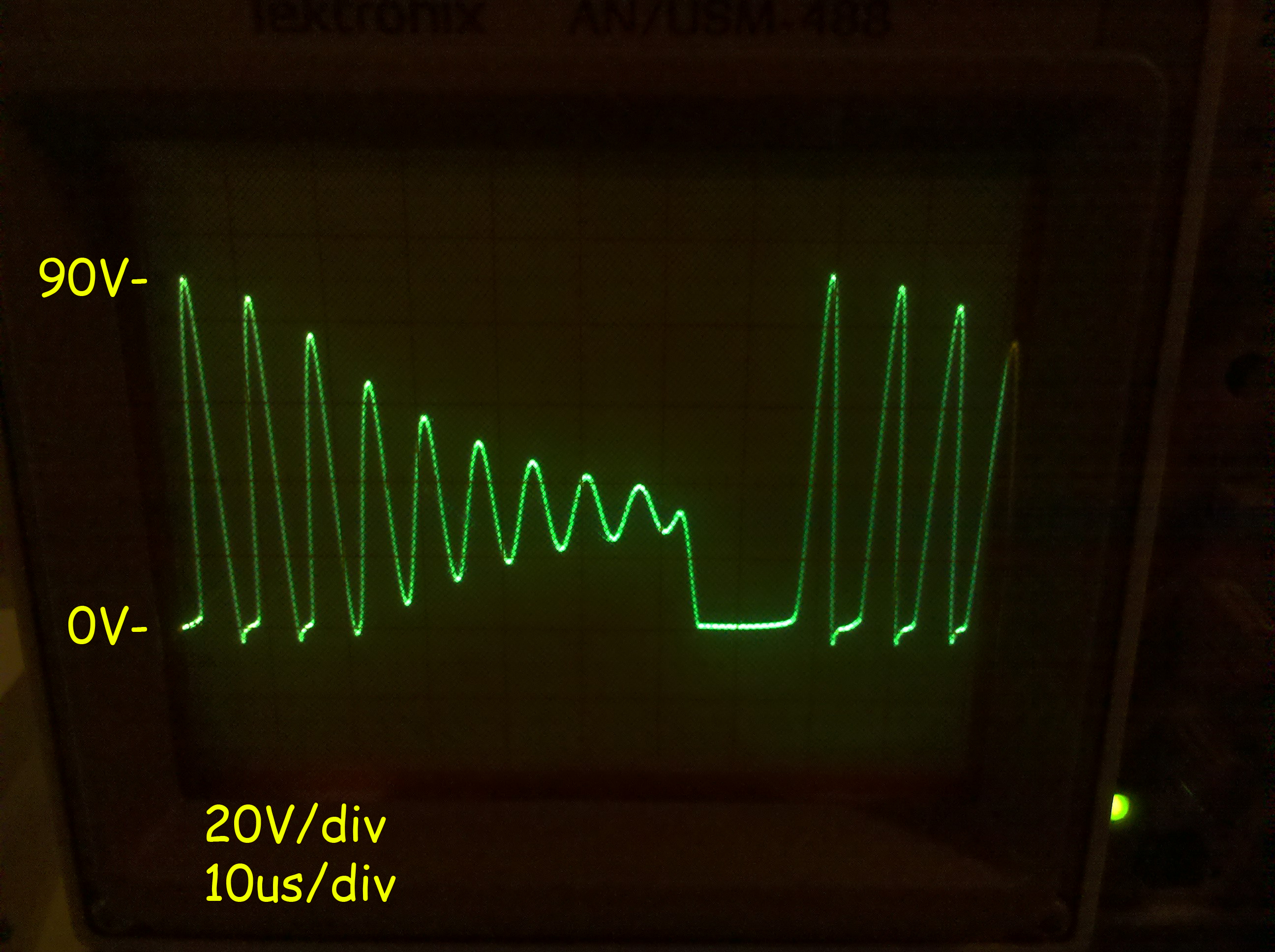
> So, with the flyback running with a 36VDC primary voltage... here is a
> picture of the collector voltage (normally not readable on a scope due
> to the 1.5KV flyback spikes, but at our lowered rail, much better.
>
> http://gamearchive.askey.org/Video_Games/Manufacturers/Atari/monitors/amplifone/raster/images/waveform_hot_padded.jpg
>
> Items of Note on this Photo:
>
> 1. I have really good ringing. If I had a short then based upon my
> understanding, ringing wouldn't be so good?
> 2. Oddly, my output voltages are indeed concerning on the
> secondaries, they are the expected ratio?
> 1. +180VDC (tap of primary) = 56V (this is about right based
> upon the ratio expected)
> 2. +24VDC = 5.2V = 21%
> 3. Filament (19VAC) = 2.5VAC = 13%
> 4. Grid (?) = 19.4V
> 5. Focus (?) = 25.5V
> 6. Anode (25KV) = didn't measure
> 3. Concerning: Is that Im only getting a 90V Peak reverse spike
> off the 36V primary... not good.. it should be higher... like
> 300V right? Something *is* damping this down it seems!!!
>
> So.. all in all... it really does seem like my flybacks are done (both
> of them). Still looking for more potentially good flybacks if anyone
> has one laying around!!!!
>
> Any comments or insights are welcome... yeah, I know I spent too much
> time on this, but Im sort of aspergery!!! :-)
>
> jess
>
> PS - again the whole enchilada is here...
>
> http://gamearchive.askey.org/Video_Games/Manufacturers/Atari/monitors/amplifone/raster/
>
>
>
>
>
>
>
>
>
>
Hi Jess,
Your ringing looks good - the decay curve is not excessive. I think the
LOPT might be OK.
When I test this I use an audio signal generator set it to about 15 kHz
and a scope or AC voltmeter on one of the output windings.
Connect the generator to the leads that the horizontal output transistor
and ground use (out of circuit, use HOT and B+ leads --- sam). You
should see on the scope a reasonably nice waveform similar to the input.
If you are using a voltmeter, you should get approximately the correct
ratio output voltage relative to the original voltages. So if your
generator puts out 10 VAC and the original HV input levels were 100 VDC,
then the voltage levels should be about 1/10th of the original. I do
this in-circuit, and try to get a square wave as the source, but the
theory is consistent.
Your switching supply needs a load to regulate. So use ohms law to
figure out a resistor (the PIRE wheel to figure out its wattage) that
will be about 1/2 the expected load (1A fuse test with 1/2A load = 2X
Voltage = R) to see if it actually is putting out some power. 76 volts @
1/2A is a 152R resistor.
Once power supply is ok then remove load resistor, then connect power
back to deflection PCB and, leaving the flyback disconnected, listen for
yoke chatter - indicating deflection.
John :-#)#
--
John's Jukes Ltd. 2343 Main St., Vancouver, BC, Canada V5T 3C9
Call (604)872-5757 or Fax 872-2010 (Pinballs, Jukes, VideoGames)
                 www.flippers.com
"Old pinballers never die, they just flip out"
---------------------------------------------------------------------------
** Unsubscribe, subscribe, or view the archives at http://www.vectorlist.org
** Please direct other questions, comments, or problems to chris@westnet.com
Received on Mon Jan 17 02:29:28 2011
This archive was generated by hypermail 2.1.8 : Mon Jan 17 2011 - 03:50:00 EST