Okay, I put the standalone LOPT onto my square wave generator
(unfortunately my generator can only supply 30ma) so Im not sure that is
enough.
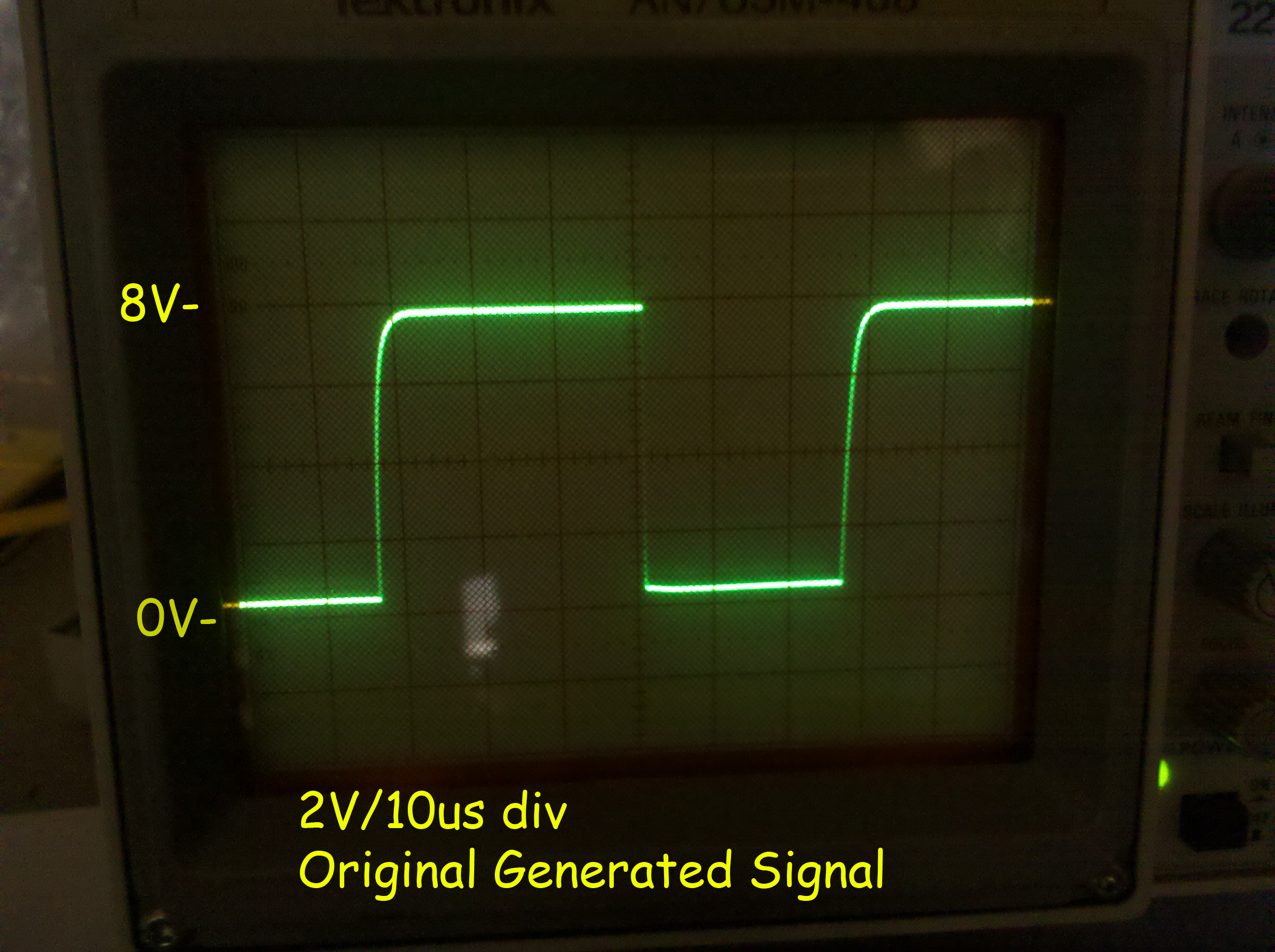
Here is the signal before attaching the LOPT.... 15KHz 9vP-P
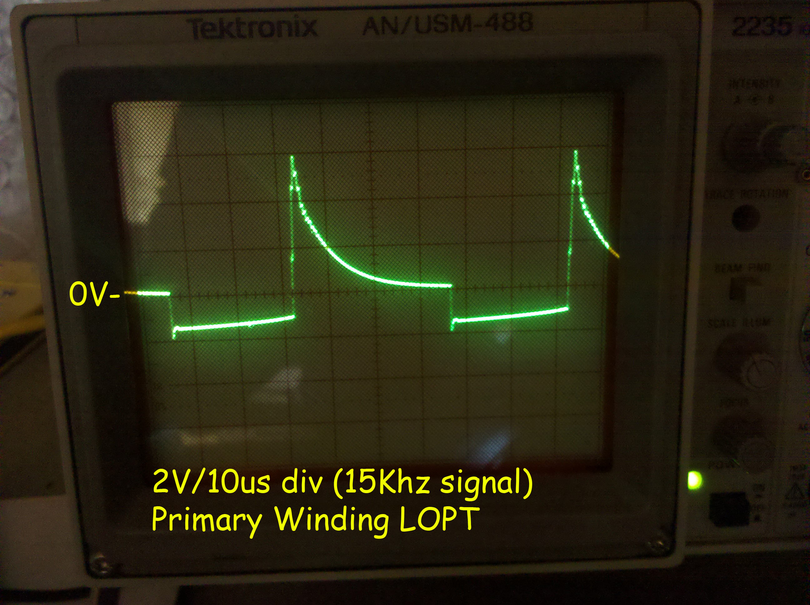
Here is the primary with that signal attached... secondaries are exactly
the same waveform, yet in different ratios (and those ratios are not
correct)
Doesn't look right.
When I read a DC voltage on the Anode cap, I have 2.2VDC, pretty low. :-(
On 1/17/2011 12:36 PM, John Robertson wrote:
> Jess Askey wrote:
>> From what I read, I figure that if there was a short the Q would be
>> lowered enough that I wouldn't get any ringing... even in circuit.
>> However, with that said, since my ringing is drastically *lower* than
>> I expect (I thought there should be a 300V oscillation on the
>> collector with a 36V supply), something is dragging this down.... so
>> I think it is simply ringing at the expense of excessive current
>> because the Q *is* lower.
>>
>> I will try the low voltage out of circuit ring test today and report
>> back... with the low amounts of current, Im guessing that I will not
>> get a *good* ring out of it.
>>
>> jess
>>
>>
>> On 1/17/2011 12:56 AM, Rodger Boots wrote:
>>>
>>> John, it's a raster monitor, not vector.
>>>
>>> So why is it ringing in the first place? Is the damper diode
>>> connected? Is the horizonal output transistor the correct part? Is
>>> the correct yoke winding connected? Is the filter capacitor on the
>>> power supply to the output transformer working (should be DC to the
>>> transformer, very little AC).
>>>
>> ---------
>
>
> Have you checked your input bridge yet (4x 1N4004) as well as the 12V
> regulator U4(78L12) (not too likely, but if shorted then Q7 is also
> bad) for damage from the un-isolated 120VAC power test you did? PTC1
> should be fine - no connection to ground there. Pg 54 of schematic PDF.
>
> I would separate the flyback from the circuit and then hook up pins 1
> (common) and 4 (pulsing DC) to some AC supply using a bridge rectifier
> to get pulsing DC running at the correct frequency (otherwise the
> transformer is not efficient - results will be skewed lower). Hook a
> scope up to pins 1 & 4 to see the picture, it should be fairly clean.
>
> Then scope pin 5 to see if you have a bit of a boost on the pulsing
> DC, next scope across pins 7 (probe) & 9 (common) should show AC about
> 15-20% of the original input voltage (120/24), pins 6 & 9 showing
> around 5% (filament of 6.3VAC). You can also use a HV probe (if you
> have one) for the HV output, again it should be the ratio of your test
> voltage to 120V.
>
> John :-#)#
>
---------------------------------------------------------------------------
** Unsubscribe, subscribe, or view the archives at http://www.vectorlist.org
** Please direct other questions, comments, or problems to chris@westnet.com
Received on Mon Jan 17 15:21:13 2011
This archive was generated by hypermail 2.1.8 : Mon Jan 17 2011 - 16:50:00 EST