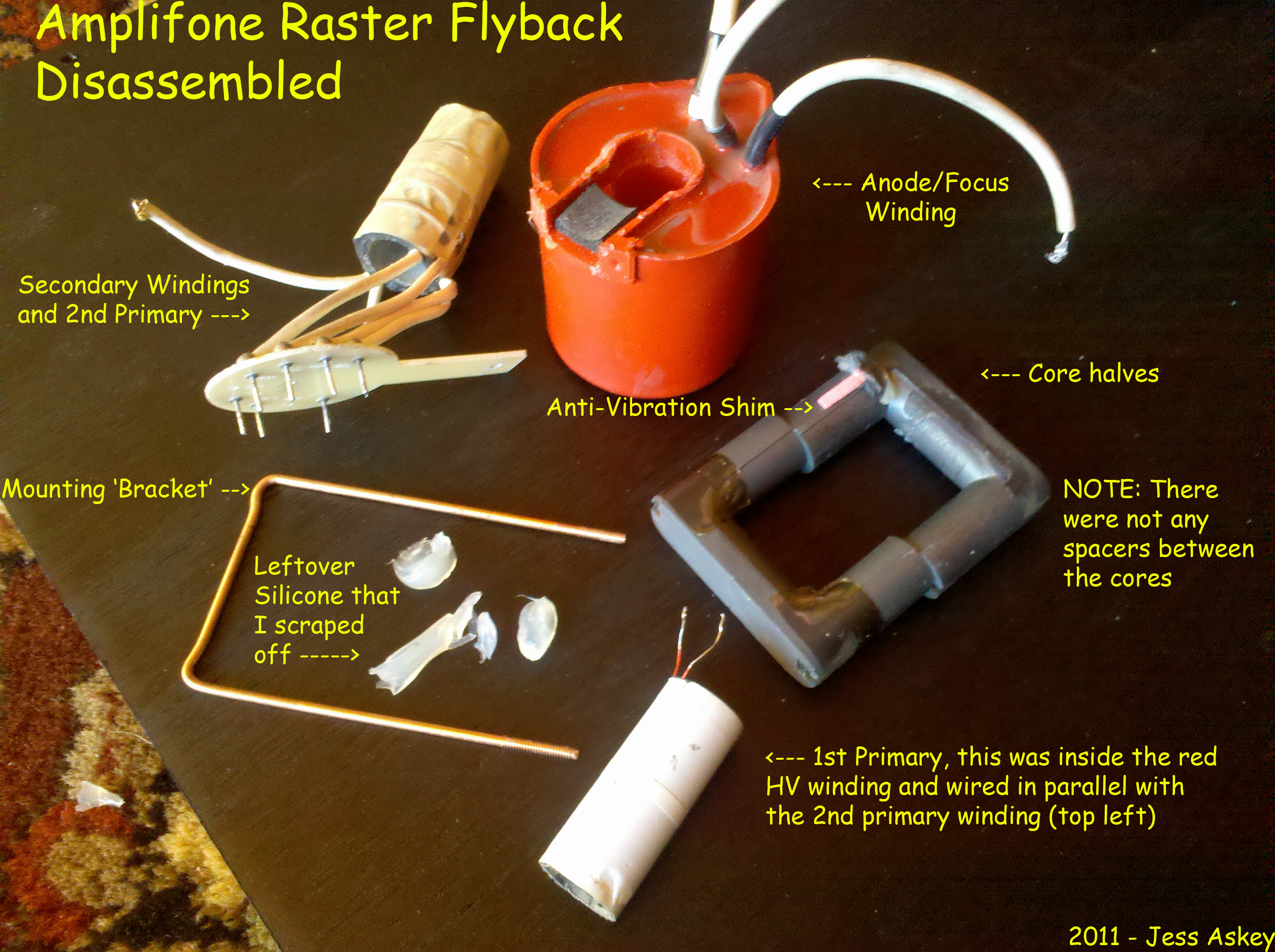
Well, you know me.... Mr Impatient.. already disassembled... (Dude..
my Dad is a TV repairman, we can fix it!)
I can also ring each individual winding this way too and find out
*exactly* what is wrong.
On 1/17/2011 2:16 PM, John Robertson wrote:
> Jess Askey wrote:
>> but I don't think that is the waveform that I was supposed to be
>> seeing.... Im supposed to see something more like this...
>>
>> http://www.djlewis.us/files/electronics/blue/ringtest.jpg
>>
>> plus, given that I was putting in 8V that should have put my anode
>> voltage more like 1500V or at least higher than 2V. :-)
>>
>> I think that one of the windings must be shorted.
>>
>> Time to disect the flyback.
>
> Lets not take the flyback apart just yet...
>
> As Roger points out the image appears more or less correct for your
> situation. A normal HV transformer/flyback receives a very short pulse
> for a rather short duty cycle. Your duty cycle is 50% and this covers
> up the ringing. What is the output like on pins 7 & 9?
>
> I'll pull out some flybacks and see what I get for similar setups in
> the next day or three.
>
> John :-#)#
>>
>> On 1/17/2011 1:26 PM, Rodger Boots wrote:
>>>
>>> Seems reasonable to me. HV is going to be nearly nonexistent with
>>> that low of primary drive.
>>>
>>> On Jan 17, 2011 2:21 PM, "Jess Askey" <jess@askey.org
>>> <mailto:jess@askey.org>> wrote:
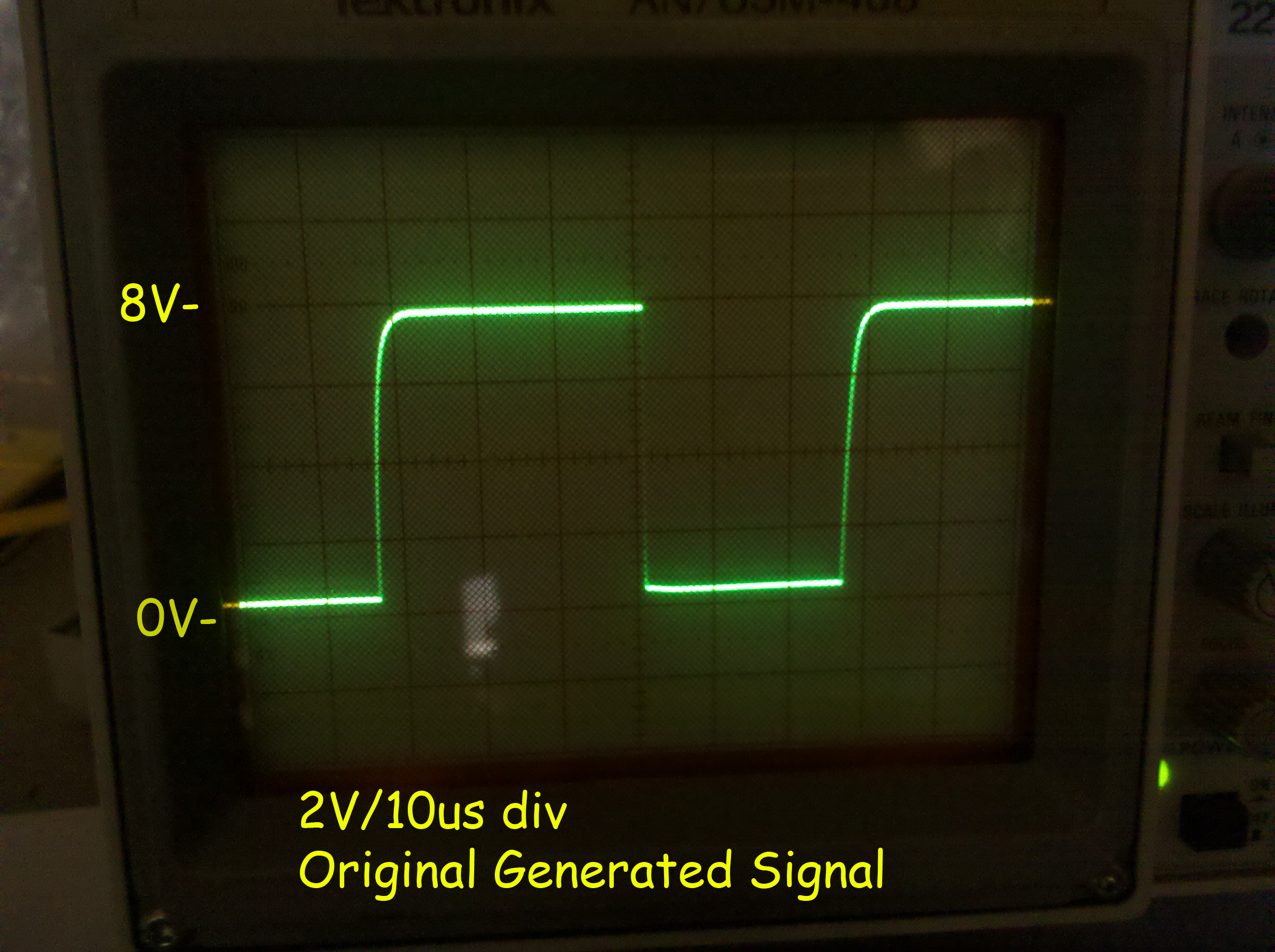
>>> > Okay, I put the standalone LOPT onto my square wave generator
>>> > (unfortunately my generator can only supply 30ma) so Im not sure
>>> that is
>>> > enough.
>>> >
>>> > Here is the signal before attaching the LOPT.... 15KHz 9vP-P
>>> >
>>> >
>>> http://gamearchive.askey.org/Video_Games/Manufacturers/Atari/monitors/amplifone/raster/images/generator_output_15k.jpg
>>> >
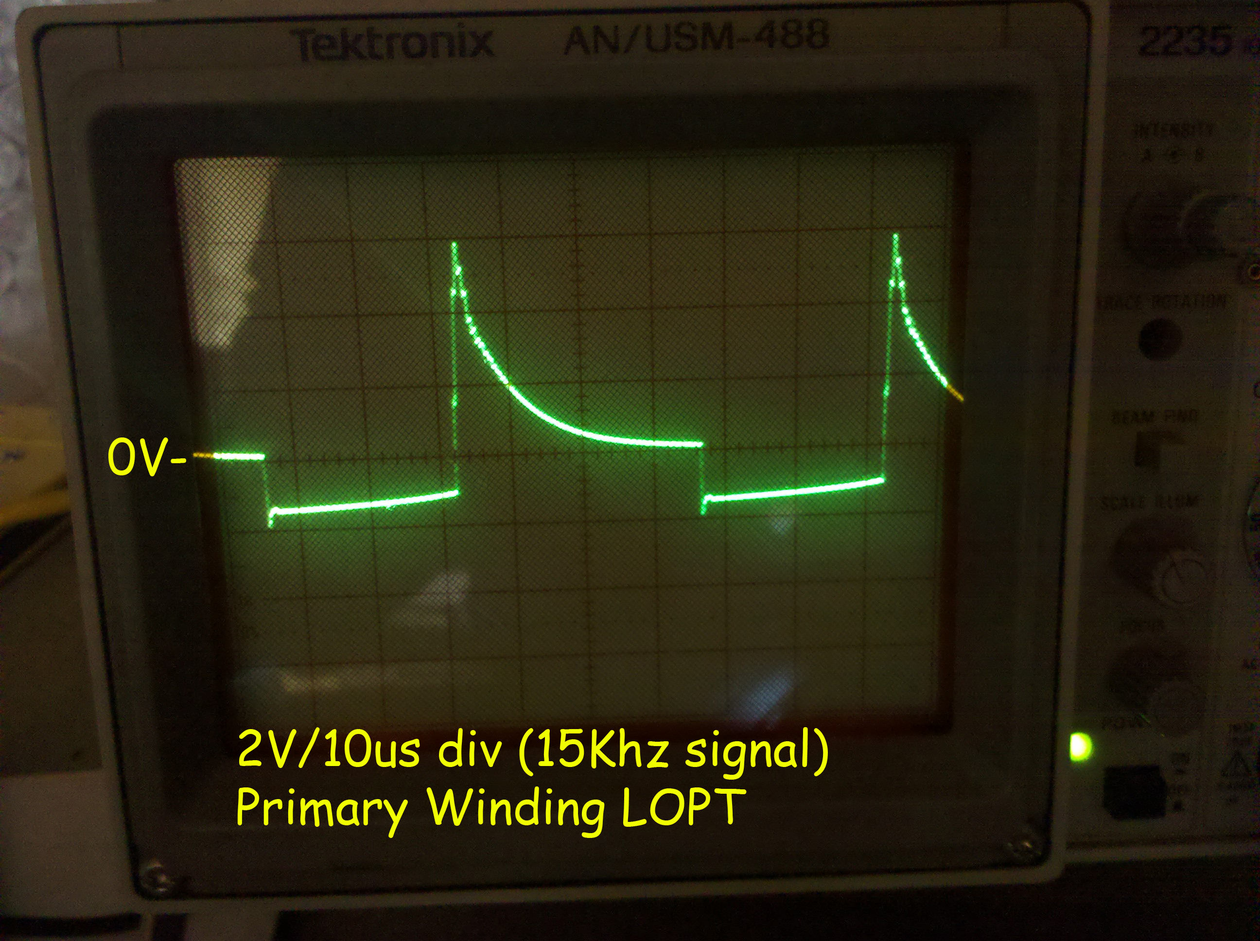
>>> > Here is the primary with that signal attached... secondaries are
>>> exactly
>>> > the same waveform, yet in different ratios (and those ratios are not
>>> > correct)
>>> >
>>> >
>>> http://gamearchive.askey.org/Video_Games/Manufacturers/Atari/monitors/amplifone/raster/images/lopt_ringing_15k.jpg
>>> >
>>> > Doesn't look right.
>>> >
>>> > When I read a DC voltage on the Anode cap, I have 2.2VDC, pretty
>>> low. :-(
>>> >
>>> >
>>> >
>>> > On 1/17/2011 12:36 PM, John Robertson wrote:
>>> >> Jess Askey wrote:
>>> >>> From what I read, I figure that if there was a short the Q would be
>>> >>> lowered enough that I wouldn't get any ringing... even in circuit.
>>> >>> However, with that said, since my ringing is drastically *lower*
>>> than
>>> >>> I expect (I thought there should be a 300V oscillation on the
>>> >>> collector with a 36V supply), something is dragging this
>>> down.... so
>>> >>> I think it is simply ringing at the expense of excessive current
>>> >>> because the Q *is* lower.
>>> >>>
>>> >>> I will try the low voltage out of circuit ring test today and
>>> report
>>> >>> back... with the low amounts of current, Im guessing that I will
>>> not
>>> >>> get a *good* ring out of it.
>>> >>>
>>> >>> jess
>>> >>>
>>> >>>
>>> >>> On 1/17/2011 12:56 AM, Rodger Boots wrote:
>>> >>>>
>>> >>>> John, it's a raster monitor, not vector.
>>> >>>>
>>> >>>> So why is it ringing in the first place? Is the damper diode
>>> >>>> connected? Is the horizonal output transistor the correct part? Is
>>> >>>> the correct yoke winding connected? Is the filter capacitor on the
>>> >>>> power supply to the output transformer working (should be DC to
>>> the
>>> >>>> transformer, very little AC).
>>> >>>>
>>> >>> ---------
>>> >>
>>> >>
>>> >> Have you checked your input bridge yet (4x 1N4004) as well as the
>>> 12V
>>> >> regulator U4(78L12) (not too likely, but if shorted then Q7 is also
>>> >> bad) for damage from the un-isolated 120VAC power test you did? PTC1
>>> >> should be fine - no connection to ground there. Pg 54 of
>>> schematic PDF.
>>> >>
>>> >> I would separate the flyback from the circuit and then hook up
>>> pins 1
>>> >> (common) and 4 (pulsing DC) to some AC supply using a bridge
>>> rectifier
>>> >> to get pulsing DC running at the correct frequency (otherwise the
>>> >> transformer is not efficient - results will be skewed lower). Hook a
>>> >> scope up to pins 1 & 4 to see the picture, it should be fairly clean.
>>> >>
>>> >> Then scope pin 5 to see if you have a bit of a boost on the pulsing
>>> >> DC, next scope across pins 7 (probe) & 9 (common) should show AC
>>> about
>>> >> 15-20% of the original input voltage (120/24), pins 6 & 9 showing
>>> >> around 5% (filament of 6.3VAC). You can also use a HV probe (if you
>>> >> have one) for the HV output, again it should be the ratio of your
>>> test
>>> >> voltage to 120V.
>>> >>
>>> >> John :-#)#
>>> >>
>>> >
>>> ---------------------------------------------------------------------------
>>> > ** Unsubscribe, subscribe, or view the archives at
>>> http://www.vectorlist.org
>>> > ** Please direct other questions, comments, or problems to
>>> chris@westnet.com <mailto:chris@westnet.com>
>
>
> --
> John's Jukes Ltd. 2343 Main St., Vancouver, BC, Canada V5T 3C9
> Call (604)872-5757 or Fax 872-2010 (Pinballs, Jukes, VideoGames)
> www.flippers.com
> "Old pinballers never die, they just flip out"
---------------------------------------------------------------------------
** Unsubscribe, subscribe, or view the archives at http://www.vectorlist.org
** Please direct other questions, comments, or problems to chris@westnet.com
Received on Mon Jan 17 16:33:28 2011
This archive was generated by hypermail 2.1.8 : Mon Jan 17 2011 - 16:50:00 EST