|
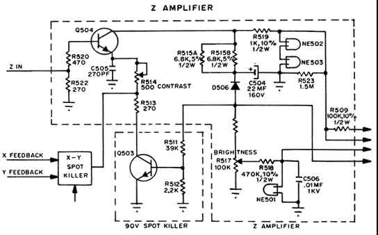
The Z amplifier provides intensity modulation of the elec- tron beam. A minimum 8 steps are discernable. The driv- ing generator must be capable of the following outputs into a 270 ohm load: 4.0 volts full beam intensity dB point of 10 MHz capable of sufficient amplification to control the electron beam, typically 30V P-P of signal may be found on the cathode of the CRT. R514 is a con- trast control and varies the AC gain over a range of 3/1. C505 is a peaking capacitor selected for good high fre- quency response with minimum overshoot. Brightness is controlled by the DC bias voltage between cathode and G1 of CRT, with G1 being the most negative with respect to cathode. It is set by a divider network comprised of R516 and brightness control R517. In order |
to accomodate the large differences in turn on characteristics of CRT, brightness control range should be about 25% or more. This means that on most tubes it is now possible to turn this control up to the point where an undeflected beam may be seen on the screen. Care must be used when adjusting this control because should this occur, the probability is high that phosphor will burn and irreversible CRT damage will result in short order. R518, C506 and NE501 are a spark supression network to keep any transient voltage spikes that may be generated inside the CRT due to internal arcing from damaging the Z amp by routing them to ground R519, NE502 and NE503 are also are suppression components. The two neons have a combined firing voltage of approximately 130 volts. Any voltage spike greater than 130 volts will trigger the neons and provide a very low impedance path to ground. |