|
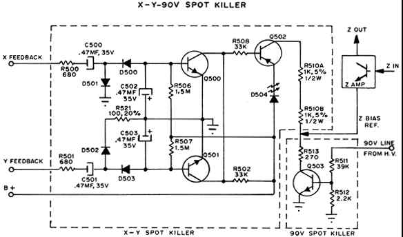
It is important to protect CRT from phosphor burn by an undeflected brite spot on screen under different fault conditions. This can be done by cutting off electron beam (2 amplifier) and also by allowing the CRT heater to cool down before the cathode to G1 bias voltage becomes small enough to turn on the electron beam on screen depending upon different fault conditions. A typical cathode to G1 voltage for a just visible display is 60 volts. D506 is an isolation diode to prevent discharge of C504 through any resistance path in H.V. supply and brightness control circuitry. Following are examples of typical fault conditions. A. On power down, 2 is cut of as Q503 and Q504 are not conducting, while D506 blocks discharge path of C504 long enough to hold cathode voltage until heater filament cools down. B. On +90 volts failure, Q503 is turned off, which in turn cuts off Q504 while the cathode of the CRT will reach the 95V supply potential. Since Z is cut off and cathode is at 95V supply potential, this will eliminate any phosphor burn on CRT. |
C. Spot killer circuit is also intended to protect CRT in case of X or Y or both amplifier circuits fail. Q500 and 0501 are X and Y spot killer amplifiers. Since both work same way, only 4500 circuit has been analyzed here. Under normal operating condition feedback input signals of approximately 2.8V PIP from yoke are being rectified by D500, D501 to - 4.7 volts. This will overcome comparatively small +ve bias from R506 and reverse bias Q500. Under fault condition, there will be no input signal and -ve supply on base of Q500. Positive bias will take over and turns on Q500, Q502. LED D504 will come on and in- dicate fault condition in amplifier circuit. Collector current of Q502 will develop sufficient voltage across R513 to reverse bias, the emitter base junc- tion of Q504. With Q504 in cutoff, the cathode of the CRT will reach the 95V supply potential. Since Z is cut off and cathode is at 95V supply potential, this will eliminate phosphur burn on CRT. |