Okay, this is looking better now....
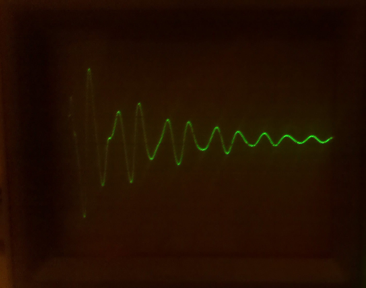
This is the best I could lock onto the ringing at the tip of the main
pulse... this is *very* zoomed in (.2us/div) and I couldn't quite get it
to trigger ahead of the main pulse. Apologies for the crappy lighting...
.... but is exactly what I should see. This is pulled off one of the
secondaries.
Additionally: I was feeding my primary with 10VPP. Upon measuring my
secondaries, they all came out just about right comparing to the
computed ratios from 120V down to 10V. I even had a whopping 50VDC on my
anode.
So: Seems this transformer must be good. Pretty exciting that I had it
taken apart to the extent that I did and managed to get to back together
(quite easily too). I will re-silicone it tomorrow and move back to
troubleshooting the support circuitry. Since I have another flyback and
my test rig is stable, I will ring that one tomorrow too and then report
back.
Has anyone run into either the deflection capacitor or the retrace
capacitor breaking down at operating voltages? I still can't believe
that I have two PCB's with the same problem. Shit, maybe my picture tube
has a short? Can I run a flyback with the Anode and focus disconnected?
thanks for staying late at the party!!
jess
On 1/17/2011 5:27 PM, John Robertson wrote:
> Jess Askey wrote:
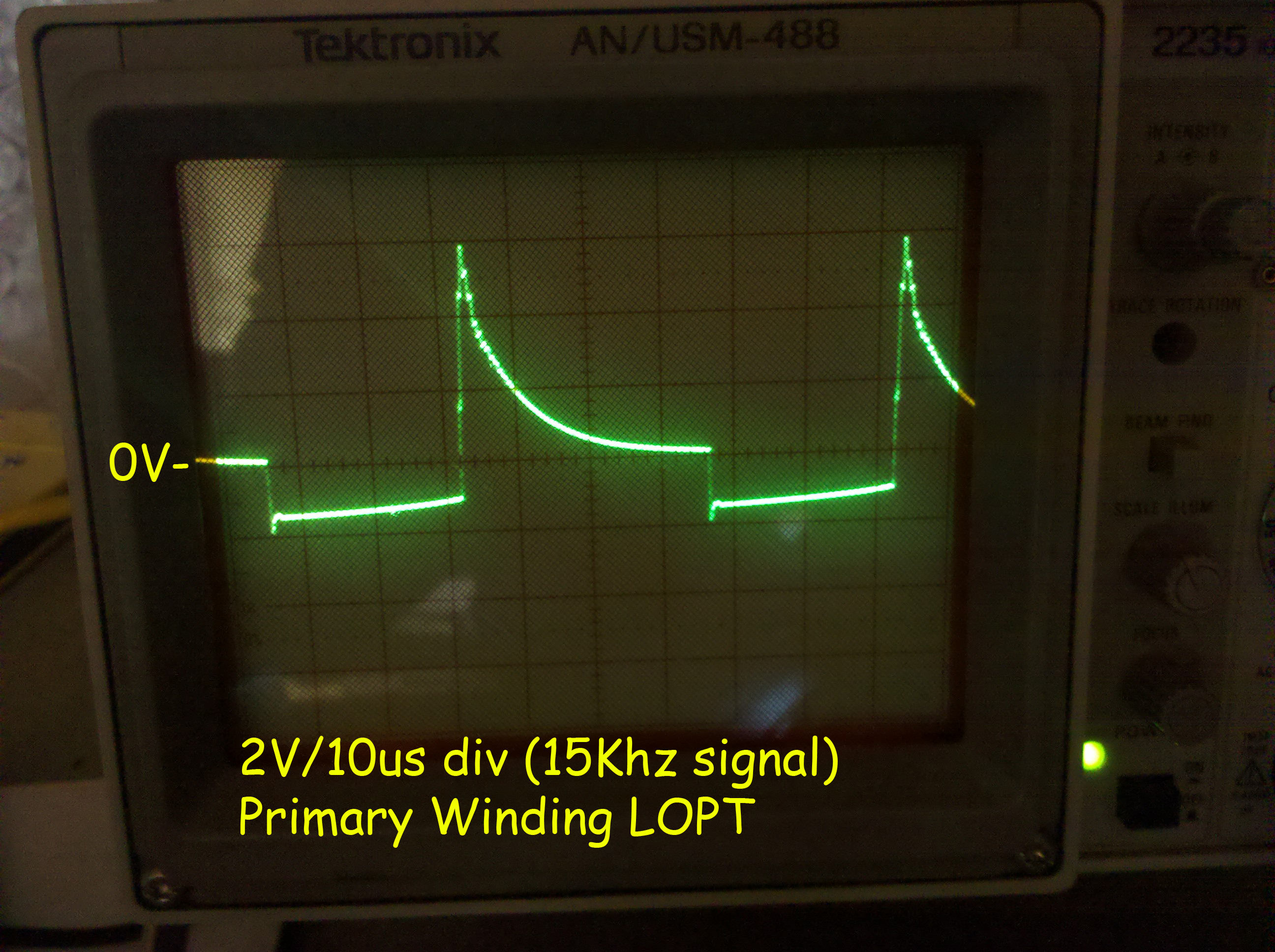
>> Here is the main primary being rung @ 15KHz with a .047uf cap in
>> series with it, there are no other windings on the core with it...
>> but I can throw more on if needed.
>>
>> http://gamearchive.askey.org/Video_Games/Manufacturers/Atari/monitors/amplifone/raster/images/main_primary_ring_no_secondaries.jpg
>>
>> I thought that Raster flybacks where supposed to have spacers between
>> the cores? This one doesn't have any.
>>
>> jess
>>
>
> That image does not look good to me, the signal is damped way too
> quickly. You should see a train of decreasing rings like the other
> picture you posted. I suspect the red coil has a shorted winding after
> all - assuming you are only driving the red coil and it is out of
> circuit as in your most recent picture above.
>
> As for the spacer, it all depends on the design. I am fairly sure most
> flybacks do NOT have a spacer between the two halves, what they
> usually do have is some sort of glue...
>
> John :-#(#
>>
>> On 1/17/2011 2:35 PM, Rodger Boots wrote:
>>> Just grab a capacitor (.1 to 1 uF or so) and put it in series with
>>> the generator output. You just need to get rid of the DC component
>>> of the signal (transformers get weird around DC).
>>>
>>>
>>> On Mon, Jan 17, 2011 at 3:19 PM, Jess Askey <jess@askey.org
>>> <mailto:jess@askey.org>> wrote:
>>>
>>> My generator doesn't have a DC offset, I will have to build one.
>>> I just have a waveform generator IC that I breadboarded up
>>> really quick... I will see if I can get a waveform generator
>>> locally that has that feature.
>>>
>>>
>>> On 1/17/2011 2:16 PM, Rodger Boots wrote:
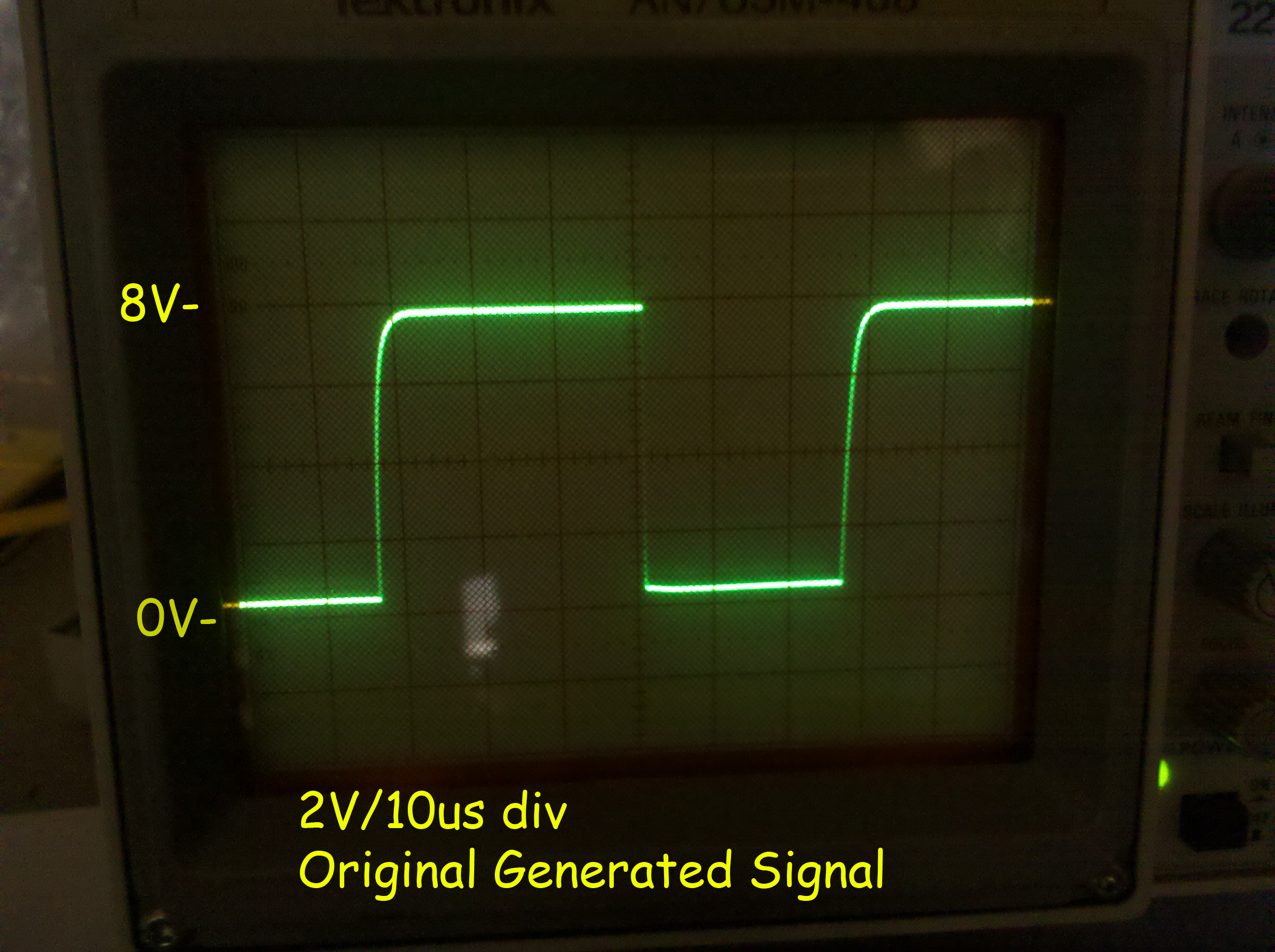
>>>> Does your generator have a knob marked "DC offset"? If so, set
>>>> it for a -4 to +4 volt square wave. Using 0 to +8 volts isn't
>>>> going to give you useful readings.
>>>>
>>>>
>>>> On Mon, Jan 17, 2011 at 2:19 PM, Jess Askey <jess@askey.org
>>>> <mailto:jess@askey.org>> wrote:
>>>>
>>>> Okay, I put the standalone LOPT onto my square wave
>>>> generator (unfortunately my generator can only supply 30ma)
>>>> so Im not sure that is enough.
>>>>
>>>> Here is the signal before attaching the LOPT.... 15KHz 9vP-P
>>>>
>>>> http://gamearchive.askey.org/Video_Games/Manufacturers/Atari/monitors/amplifone/raster/images/generator_output_15k.jpg
>>>>
>>>> Here is the primary with that signal attached...
>>>> secondaries are exactly the same waveform, yet in different
>>>> ratios (and those ratios are not correct)
>>>>
>>>> http://gamearchive.askey.org/Video_Games/Manufacturers/Atari/monitors/amplifone/raster/images/lopt_ringing_15k.jpg
>>>>
>>>> Doesn't look right.
>>>>
>>>> When I read a DC voltage on the Anode cap, I have 2.2VDC,
>>>> pretty low. :-(
>>>>
>>>
>
>
> --
> John's Jukes Ltd. 2343 Main St., Vancouver, BC, Canada V5T 3C9
> Call (604)872-5757 or Fax 872-2010 (Pinballs, Jukes, VideoGames)
> www.flippers.com
> "Old pinballers never die, they just flip out"
---------------------------------------------------------------------------
** Unsubscribe, subscribe, or view the archives at http://www.vectorlist.org
** Please direct other questions, comments, or problems to chris@westnet.com
Received on Tue Jan 18 02:26:02 2011
This archive was generated by hypermail 2.1.8 : Tue Jan 18 2011 - 11:50:00 EST