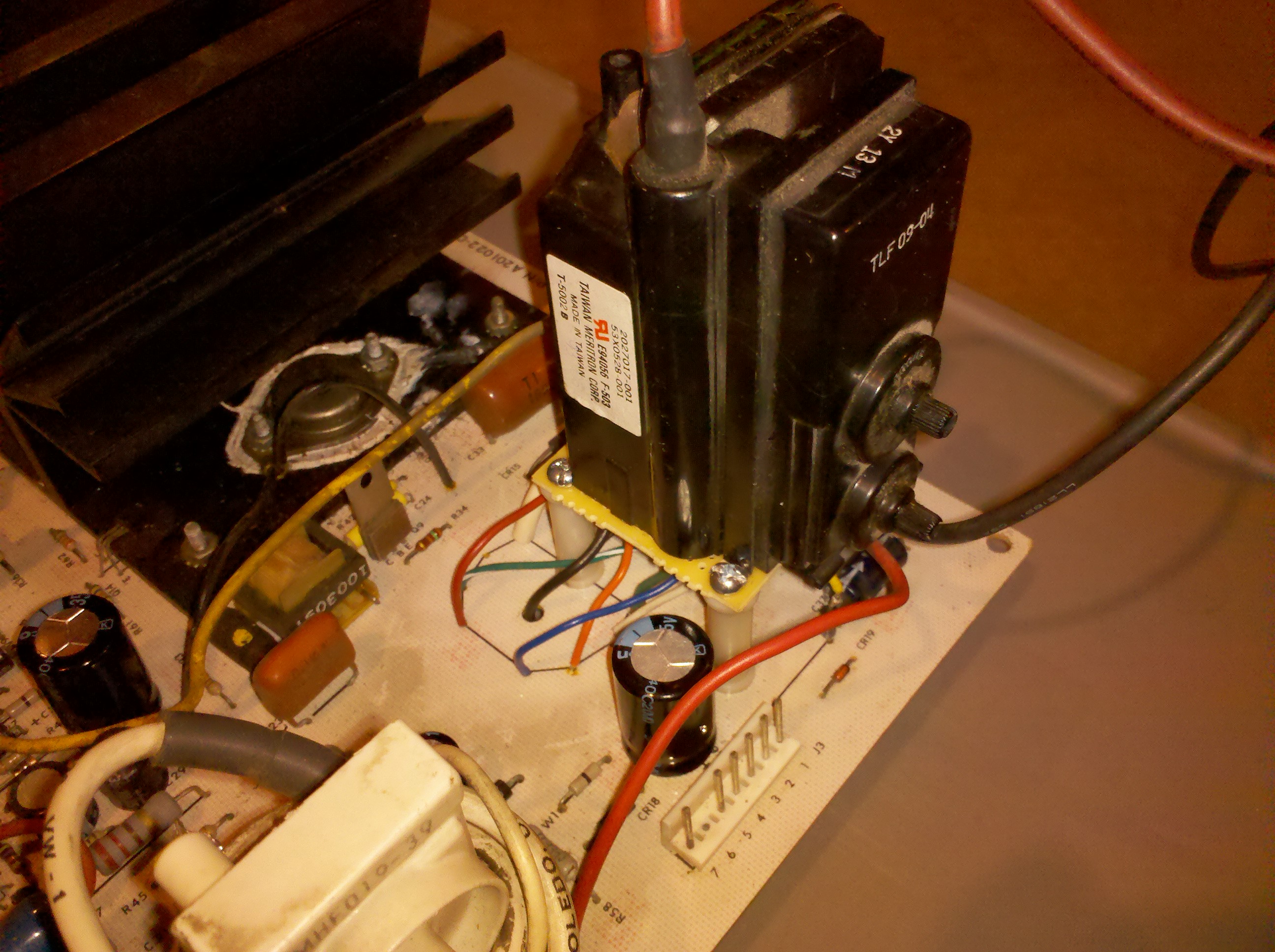
I am getting closer to a functional replacement for the stock
Amplifone Raster Flyback.
I present Frankenstein I
So far I have pretty close voltages... except my 180V is down around
130V (WG designed voltage), so I may need to find a better replacement
than the WG 53X05280-01 flyback from the K7900 chassis.
John, my anode is currently sitting at 17.81KV, however, with this
configuration I am missing two things..
1. High Voltage regulation - The amplifone deflection PCB has no
means for regulation, I will have to modify the circuit to
regulate based upon feedback from the secondary somewhere.
Otherwise, Im sure I will have some varied blooming issues?
2. High Voltage Protection - I should be able to use the built-in HV
protection, I will just have to rebias it since it uses the
current off the focus and G2 ground on the original. The WG lumps
the filament onto that ground too so it will be a bit different.
Does anyone know of a way to search for flybacks based upon
specifications? I found
http://www.donberg.ie and
http://www.hrshop.es/index.php?command=viewSection&id=4 but neither
allow searching by spec and they have thousands of flybacks to choose from.
On 1/20/2011 3:44 PM, John Robertson wrote:
> Jess Askey wrote:
>> Okay, I have a resolution to this problem... just a few more
>> breadcrumbs of info...All the previous messages in this thread ended
>> up concluding that the flyback was probably good.
>>
>> 1. I double checked all other components around the HOT on the PCB
>> or put in new ones
>> 2. After all of that I still had the supply shutdown due to overload.
>>
>> I spoke to Mark Shostak about the Cinelabs replacement he did on the
>> Vector HV transformer. His comments were...
>>
>> * The Amplifone 'ultra-tuned' transformers are extremely finicky
>> about any inductive abnormalities
>> * When in doubt, it is highly likely that the transformer is the
>> problem
>>
>> So, I found that I had some flybacks from a WG K7000 monitor laying
>> around. I thought I would try hooking up the primary only of it to
>> the Amplifone and see what happens. Well, the board came up fine and
>> I had decent 24VAC on one of the secondaries.
>>
>> Conclusions:
>>
>> 1. the Amplifone Raster Flyback *is* bad even tho it rings (I
>> think I had at least 7 solid ring pulses)
>> 2. The Wells-Gardner K7000 flyback might work as a suitable
>> replacement with PCB modifications, it has all the voltage taps
>> (filament, +24, +15, +180, focus, screen, anode) that the
>> amplifone uses.
>>
>> Im going to see if I can get the K7000 flyback working fully this
>> weekend and will report back.
>>
>> jess
>>
> Hi Jess,
>
> Interesting news, I would like to borrow one of your bad HV
> transformers to test with my LOPT/Flyback ring checker to see what it
> thinks...
>
> As for substituting, be sure to check the High Tension voltage - you
> really do not want this to be any higher than around 18KV...
>
> John :-#)#
>>
>>
>> On 1/19/2011 12:12 AM, Jess Askey wrote:
>>> Well, I put the flyback back in and removed the following loads...
>>>
>>> 1. 180V Secondary - Pulled rectifier diode
>>> 2. Filament - Pulled current limiting resistor
>>> 3. 24V Secondary - Pulled rectifier diode
>>> 4. Focus Tap - Disconnected and insulated
>>> 5. Anode - Disconnected and insulated
>>>
>>> Unfortunately, after all this the switcher still shuts down due to
>>> overcurrent. I tried disconnecting the deflection coil and it took
>>> about a half second longer to shutdown but still did. So, that
>>> pretty much removes the faults being related too ...
>>>
>>> 1. Bad Picture Tube
>>> 2. Overload on Secondary Windings
>>> 3. Deflection Coil Support Circuitry (deflection capacitor and
>>> some inductors)
>>>
>>> Pretty much the only thing left is right around the HOT at this
>>> point. (2,3 and 5 'test' okay tho)
>>>
>>> 1. HOT Discharge Capacitor (.1 @ 1600V)
>>> 2. HOT Protection Diode (0.8A 1500V rectifier)
>>> 3. HOT (BU-208)
>>> 4. T1 - HOT Driver Transformer
>>> 5. Q9 - Driver Transistor (D40P5)
>>>
>>> I am going to have to order these parts... just so I have known good
>>> ones on hand. I am using a BU-207 in one of my PCB's which should be
>>> okay, it just can't handle the same power, which isn't a problem in
>>> the 1 second it runs before shutdown.
>>>
>>> I started scoping around the HOT (base side) and T1 and the
>>> waveforms get pretty distorted away from a square wave. I can post
>>> pics of those if anyone is interested (still). :-)
>>>
>>> jess
>>>
>>> PS - I got some feedback from Mark @ Cinelabs that the Amplifone
>>> 'Ultra-Tuned' transformers are super finicky since they rely on
>>> ferro-resonance.... after doing some searching... this is explained
>>> in this patent from 1975 which explains this approach.. perhaps
>>> these flybacks are a bit different beasts??
>>> http://www.google.com/patents?hl=en&lr=&vid=USPAT3868538&id=N_o1AAAAEBAJ&oi=fnd&dq=ferro+resonant+flyback&printsec=abstract#v=onepage&q=ferro%20resonant%20flyback&f=false
>>>
>>>
>>>
>>>
>>> On 1/18/2011 9:48 AM, John Robertson wrote:
>>>> Jess Askey wrote:
>>>>> Okay, this is looking better now....
>>>>>
>>>>> This is the best I could lock onto the ringing at the tip of the
>>>>> main pulse... this is *very* zoomed in (.2us/div) and I couldn't
>>>>> quite get it to trigger ahead of the main pulse. Apologies for the
>>>>> crappy lighting...
>>>>>
>>>>> http://gamearchive.askey.org/Video_Games/Manufacturers/Atari/monitors/amplifone/raster/images/secondary_ring_15k.jpg
>>>>>
>>>>> .... but is exactly what I should see. This is pulled off one of
>>>>> the secondaries.
>>>>>
>>>>> Additionally: I was feeding my primary with 10VPP. Upon measuring
>>>>> my secondaries, they all came out just about right comparing to
>>>>> the computed ratios from 120V down to 10V. I even had a whopping
>>>>> 50VDC on my anode.
>>>>>
>>>>> So: Seems this transformer must be good. Pretty exciting that I
>>>>> had it taken apart to the extent that I did and managed to get to
>>>>> back together (quite easily too). I will re-silicone it tomorrow
>>>>> and move back to troubleshooting the support circuitry. Since I
>>>>> have another flyback and my test rig is stable, I will ring that
>>>>> one tomorrow too and then report back.
>>>>>
>>>>> Has anyone run into either the deflection capacitor or the retrace
>>>>> capacitor breaking down at operating voltages? I still can't
>>>>> believe that I have two PCB's with the same problem. Shit, maybe
>>>>> my picture tube has a short? Can I run a flyback with the Anode
>>>>> and focus disconnected?
>>>>>
>>>>> thanks for staying late at the party!!
>>>>>
>>>>> jess
>>>>>
>>>>
>>>> Hi Jess,
>>>>
>>>> I realized the reason you weren't seeing any ringing was the core
>>>> was outside of the coil so at that point all you had was a coil -
>>>> with the core in place then you would get the ringing you show
>>>> today. Figured this out after going to bed last night...
>>>>
>>>> As for running the flyback with no load on the Anode and focus
>>>> lines - no problem, I do this all the time. I have a ceramic cup on
>>>> my test bench that I stick the anode cap into when I am testing
>>>> chassis to avoid ouchies.
>>>>
>>>> John :-#)#
>>>>>
>>>>> On 1/17/2011 5:27 PM, John Robertson wrote:
>>>>>> Jess Askey wrote:
>>>>>>> Here is the main primary being rung @ 15KHz with a .047uf cap in
>>>>>>> series with it, there are no other windings on the core with
>>>>>>> it... but I can throw more on if needed.
>>>>>>>
>>>>>>> http://gamearchive.askey.org/Video_Games/Manufacturers/Atari/monitors/amplifone/raster/images/main_primary_ring_no_secondaries.jpg
>>>>>>>
>>>>>>> I thought that Raster flybacks where supposed to have spacers
>>>>>>> between the cores? This one doesn't have any.
>>>>>>>
>>>>>>> jess
>>>>>>>
>>>>>>
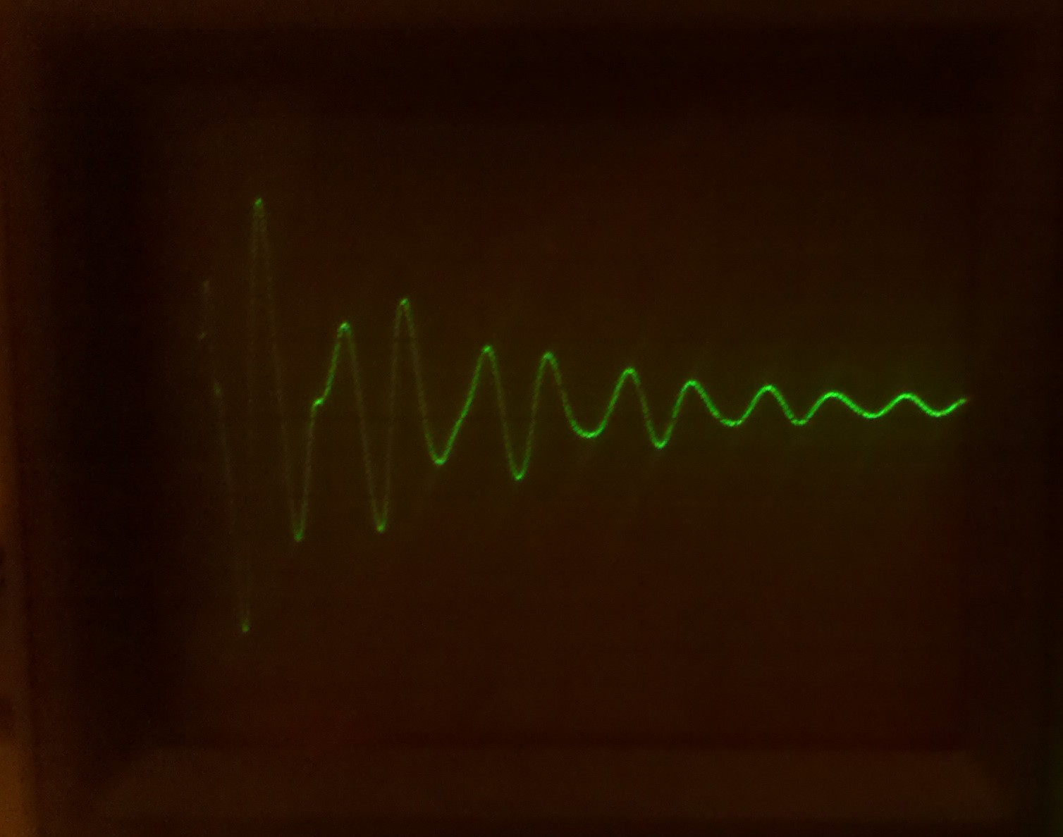
>>>>>> That image does not look good to me, the signal is damped way too
>>>>>> quickly. You should see a train of decreasing rings like the
>>>>>> other picture you posted. I suspect the red coil has a shorted
>>>>>> winding after all - assuming you are only driving the red coil
>>>>>> and it is out of circuit as in your most recent picture above.
>>>>>>
>>>>>> As for the spacer, it all depends on the design. I am fairly sure
>>>>>> most flybacks do NOT have a spacer between the two halves, what
>>>>>> they usually do have is some sort of glue...
>>>>>>
>>>>>> John :-#(#
>>>>>>>
>>>>>>> On 1/17/2011 2:35 PM, Rodger Boots wrote:
>>>>>>>> Just grab a capacitor (.1 to 1 uF or so) and put it in series
>>>>>>>> with the generator output. You just need to get rid of the DC
>>>>>>>> component of the signal (transformers get weird around DC).
>>>>>>>>
>>>>>>>>
>>>>>>>> On Mon, Jan 17, 2011 at 3:19 PM, Jess Askey <jess@askey.org
>>>>>>>> <mailto:jess@askey.org>> wrote:
>>>>>>>>
>>>>>>>> My generator doesn't have a DC offset, I will have to build
>>>>>>>> one. I just have a waveform generator IC that I
>>>>>>>> breadboarded up really quick... I will see if I can get a
>>>>>>>> waveform generator locally that has that feature.
>>>>>>>>
>>>>>>>>
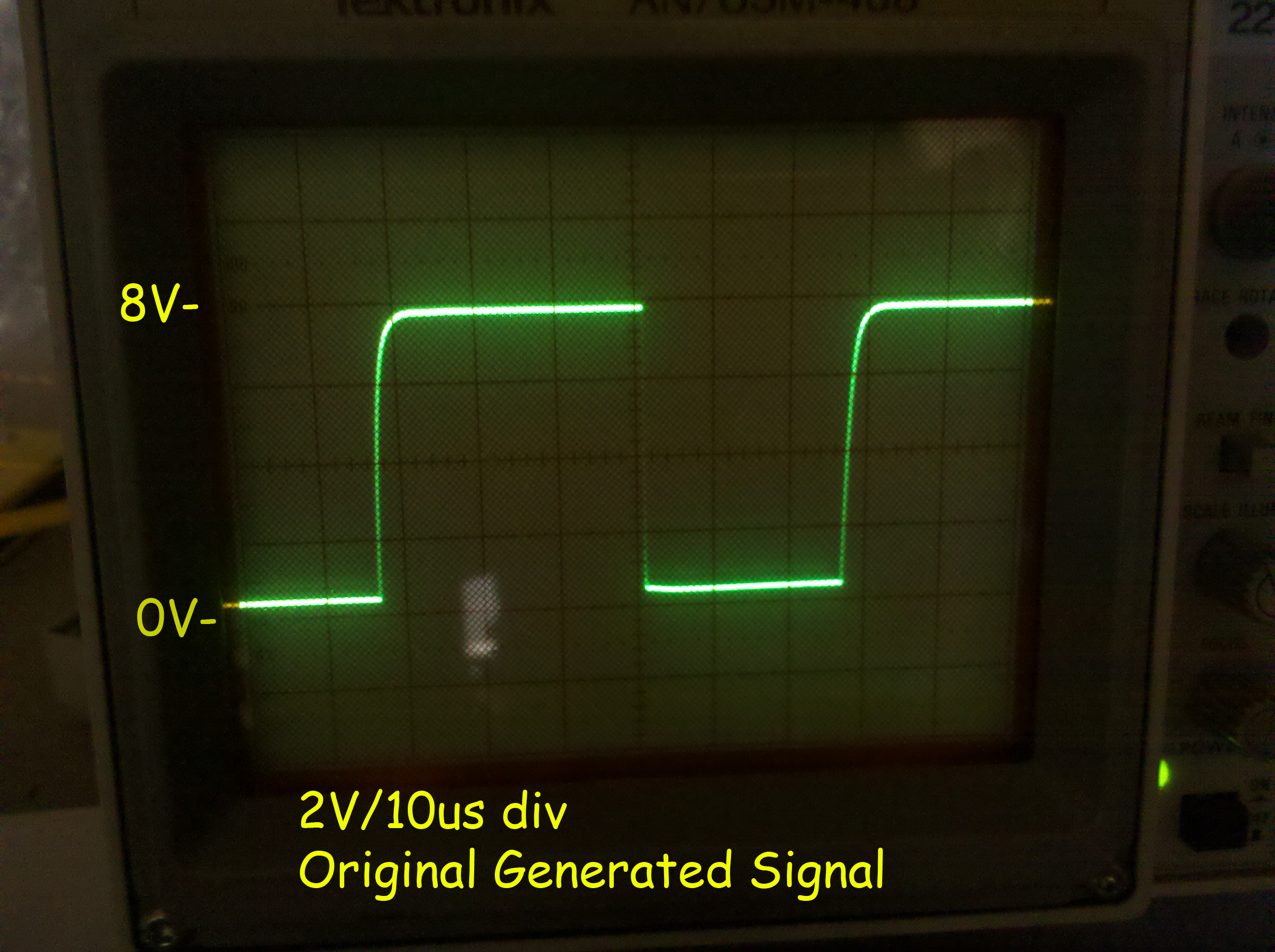
>>>>>>>> On 1/17/2011 2:16 PM, Rodger Boots wrote:
>>>>>>>>> Does your generator have a knob marked "DC offset"? If
>>>>>>>>> so, set it for a -4 to +4 volt square wave. Using 0 to +8
>>>>>>>>> volts isn't going to give you useful readings.
>>>>>>>>>
>>>>>>>>>
>>>>>>>>> On Mon, Jan 17, 2011 at 2:19 PM, Jess Askey
>>>>>>>>> <jess@askey.org <mailto:jess@askey.org>> wrote:
>>>>>>>>>
>>>>>>>>> Okay, I put the standalone LOPT onto my square wave
>>>>>>>>> generator (unfortunately my generator can only supply
>>>>>>>>> 30ma) so Im not sure that is enough.
>>>>>>>>>
>>>>>>>>> Here is the signal before attaching the LOPT.... 15KHz
>>>>>>>>> 9vP-P
>>>>>>>>>
>>>>>>>>> http://gamearchive.askey.org/Video_Games/Manufacturers/Atari/monitors/amplifone/raster/images/generator_output_15k.jpg
>>>>>>>>>
>>>>>>>>> Here is the primary with that signal attached...
>>>>>>>>> secondaries are exactly the same waveform, yet in
>>>>>>>>> different ratios (and those ratios are not correct)
>>>>>>>>>
>>>>>>>>> http://gamearchive.askey.org/Video_Games/Manufacturers/Atari/monitors/amplifone/raster/images/lopt_ringing_15k.jpg
>>>>>>>>>
>>>>>>>>> Doesn't look right.
>>>>>>>>>
>>>>>>>>> When I read a DC voltage on the Anode cap, I have
>>>>>>>>> 2.2VDC, pretty low. :-(
>>>>>>>>>
>>>>>>>>
>>>>>>
>>>>>>
>>>>>> --
>>>>>> John's Jukes Ltd. 2343 Main St., Vancouver, BC, Canada V5T 3C9
>>>>>> Call (604)872-5757 or Fax 872-2010 (Pinballs, Jukes, VideoGames)
>>>>>> www.flippers.com
>>>>>> "Old pinballers never die, they just flip out"
>>>>>>
>>>>
>>>>
>>>> --
>>>> John's Jukes Ltd. 2343 Main St., Vancouver, BC, Canada V5T 3C9
>>>> Call (604)872-5757 or Fax 872-2010 (Pinballs, Jukes, VideoGames)
>>>> www.flippers.com
>>>> "Old pinballers never die, they just flip out"
>>>>
>
>
---------------------------------------------------------------------------
** Unsubscribe, subscribe, or view the archives at http://www.vectorlist.org
** Please direct other questions, comments, or problems to chris@westnet.com
Received on Tue Jan 25 03:08:46 2011
This archive was generated by hypermail 2.1.8 : Tue Jan 25 2011 - 10:50:00 EST