Jess Askey wrote:
> I am getting closer to a functional replacement for the stock
> Amplifone Raster Flyback.
>
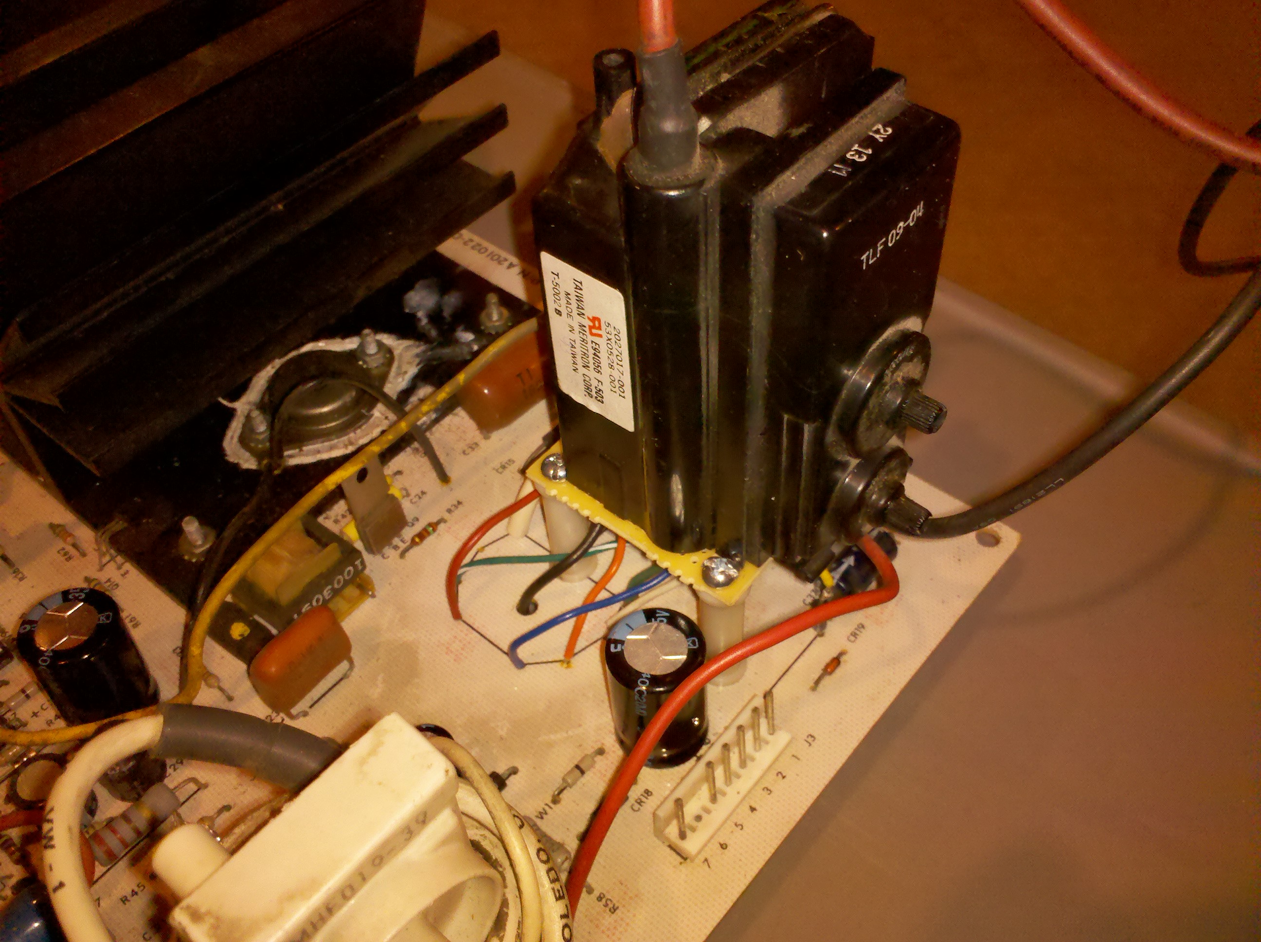
> I present Frankenstein I
>
> http://gamearchive.askey.org/Video_Games/Manufacturers/Atari/monitors/amplifone/raster/images/frankenstein_1a.jpg
>
> So far I have pretty close voltages... except my 180V is down around
> 130V (WG designed voltage), so I may need to find a better replacement
> than the WG 53X05280-01 flyback from the K7900 chassis.
>
> John, my anode is currently sitting at 17.81KV, however, with this
> configuration I am missing two things..
>
> 1. High Voltage regulation - The amplifone deflection PCB has no
> means for regulation, I will have to modify the circuit to
> regulate based upon feedback from the secondary somewhere.
> Otherwise, Im sure I will have some varied blooming issues?
> 2. High Voltage Protection - I should be able to use the built-in
> HV protection, I will just have to rebias it since it uses the
> current off the focus and G2 ground on the original. The WG
> lumps the filament onto that ground too so it will be a bit
> different.
>
> Does anyone know of a way to search for flybacks based upon
> specifications? I found
>
> http://www.donberg.ie and
> http://www.hrshop.es/index.php?command=viewSection&id=4 but neither
> allow searching by spec and they have thousands of flybacks to choose
> from.
>
>
Dropping http://www.hrshop.es/index.php?command=viewSection&id=4 into
the Google search bar gives you a translated page option - the bottom of
the English version of the page has a contact link ("request new
equivalent HR") if you can't find the transformer you need by searching
for part numbers or model numbers of the TV/Computer Monitor that the
flyback came from.
Perhaps they at least deal in English if you send a note...I would
imagine this is a 'low significance' or 'unknown significance' request,
unfortunately, so it is hard to say how interested they will be in
responding.
John :-#)#
>
>
> On 1/20/2011 3:44 PM, John Robertson wrote:
>> Jess Askey wrote:
>>> Okay, I have a resolution to this problem... just a few more
>>> breadcrumbs of info...All the previous messages in this thread ended
>>> up concluding that the flyback was probably good.
>>>
>>> 1. I double checked all other components around the HOT on the
>>> PCB or put in new ones
>>> 2. After all of that I still had the supply shutdown due to overload.
>>>
>>> I spoke to Mark Shostak about the Cinelabs replacement he did on the
>>> Vector HV transformer. His comments were...
>>>
>>> * The Amplifone 'ultra-tuned' transformers are extremely finicky
>>> about any inductive abnormalities
>>> * When in doubt, it is highly likely that the transformer is the
>>> problem
>>>
>>> So, I found that I had some flybacks from a WG K7000 monitor laying
>>> around. I thought I would try hooking up the primary only of it to
>>> the Amplifone and see what happens. Well, the board came up fine and
>>> I had decent 24VAC on one of the secondaries.
>>>
>>> Conclusions:
>>>
>>> 1. the Amplifone Raster Flyback *is* bad even tho it rings (I
>>> think I had at least 7 solid ring pulses)
>>> 2. The Wells-Gardner K7000 flyback might work as a suitable
>>> replacement with PCB modifications, it has all the voltage
>>> taps (filament, +24, +15, +180, focus, screen, anode) that the
>>> amplifone uses.
>>>
>>> Im going to see if I can get the K7000 flyback working fully this
>>> weekend and will report back.
>>>
>>> jess
>>>
>> Hi Jess,
>>
>> Interesting news, I would like to borrow one of your bad HV
>> transformers to test with my LOPT/Flyback ring checker to see what it
>> thinks...
>>
>> As for substituting, be sure to check the High Tension voltage - you
>> really do not want this to be any higher than around 18KV...
>>
>> John :-#)#
>>>
>>>
>>> On 1/19/2011 12:12 AM, Jess Askey wrote:
>>>> Well, I put the flyback back in and removed the following loads...
>>>>
>>>> 1. 180V Secondary - Pulled rectifier diode
>>>> 2. Filament - Pulled current limiting resistor
>>>> 3. 24V Secondary - Pulled rectifier diode
>>>> 4. Focus Tap - Disconnected and insulated
>>>> 5. Anode - Disconnected and insulated
>>>>
>>>> Unfortunately, after all this the switcher still shuts down due to
>>>> overcurrent. I tried disconnecting the deflection coil and it took
>>>> about a half second longer to shutdown but still did. So, that
>>>> pretty much removes the faults being related too ...
>>>>
>>>> 1. Bad Picture Tube
>>>> 2. Overload on Secondary Windings
>>>> 3. Deflection Coil Support Circuitry (deflection capacitor and
>>>> some inductors)
>>>>
>>>> Pretty much the only thing left is right around the HOT at this
>>>> point. (2,3 and 5 'test' okay tho)
>>>>
>>>> 1. HOT Discharge Capacitor (.1 @ 1600V)
>>>> 2. HOT Protection Diode (0.8A 1500V rectifier)
>>>> 3. HOT (BU-208)
>>>> 4. T1 - HOT Driver Transformer
>>>> 5. Q9 - Driver Transistor (D40P5)
>>>>
>>>> I am going to have to order these parts... just so I have known
>>>> good ones on hand. I am using a BU-207 in one of my PCB's which
>>>> should be okay, it just can't handle the same power, which isn't a
>>>> problem in the 1 second it runs before shutdown.
>>>>
>>>> I started scoping around the HOT (base side) and T1 and the
>>>> waveforms get pretty distorted away from a square wave. I can post
>>>> pics of those if anyone is interested (still). :-)
>>>>
>>>> jess
>>>>
>>>> PS - I got some feedback from Mark @ Cinelabs that the Amplifone
>>>> 'Ultra-Tuned' transformers are super finicky since they rely on
>>>> ferro-resonance.... after doing some searching... this is explained
>>>> in this patent from 1975 which explains this approach.. perhaps
>>>> these flybacks are a bit different beasts??
>>>> http://www.google.com/patents?hl=en&lr=&vid=USPAT3868538&id=N_o1AAAAEBAJ&oi=fnd&dq=ferro+resonant+flyback&printsec=abstract#v=onepage&q=ferro%20resonant%20flyback&f=false
>>>>
>>>>
>>>>
>>>>
>>>> On 1/18/2011 9:48 AM, John Robertson wrote:
>>>>> Jess Askey wrote:
>>>>>> Okay, this is looking better now....
>>>>>>
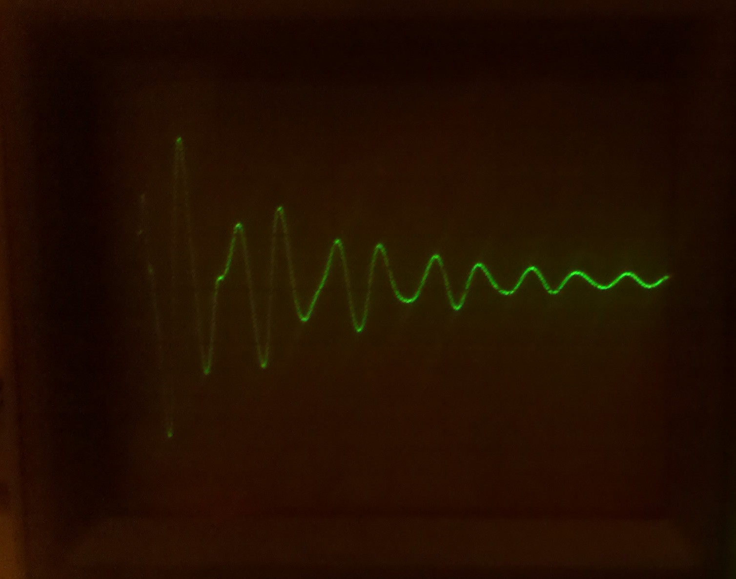
>>>>>> This is the best I could lock onto the ringing at the tip of the
>>>>>> main pulse... this is *very* zoomed in (.2us/div) and I couldn't
>>>>>> quite get it to trigger ahead of the main pulse. Apologies for
>>>>>> the crappy lighting...
>>>>>>
>>>>>> http://gamearchive.askey.org/Video_Games/Manufacturers/Atari/monitors/amplifone/raster/images/secondary_ring_15k.jpg
>>>>>>
>>>>>> .... but is exactly what I should see. This is pulled off one of
>>>>>> the secondaries.
>>>>>>
>>>>>> Additionally: I was feeding my primary with 10VPP. Upon measuring
>>>>>> my secondaries, they all came out just about right comparing to
>>>>>> the computed ratios from 120V down to 10V. I even had a whopping
>>>>>> 50VDC on my anode.
>>>>>>
>>>>>> So: Seems this transformer must be good. Pretty exciting that I
>>>>>> had it taken apart to the extent that I did and managed to get to
>>>>>> back together (quite easily too). I will re-silicone it tomorrow
>>>>>> and move back to troubleshooting the support circuitry. Since I
>>>>>> have another flyback and my test rig is stable, I will ring that
>>>>>> one tomorrow too and then report back.
>>>>>>
>>>>>> Has anyone run into either the deflection capacitor or the
>>>>>> retrace capacitor breaking down at operating voltages? I still
>>>>>> can't believe that I have two PCB's with the same problem. Shit,
>>>>>> maybe my picture tube has a short? Can I run a flyback with the
>>>>>> Anode and focus disconnected?
>>>>>>
>>>>>> thanks for staying late at the party!!
>>>>>>
>>>>>> jess
>>>>>>
>>>>>
>>>>> Hi Jess,
>>>>>
>>>>> I realized the reason you weren't seeing any ringing was the core
>>>>> was outside of the coil so at that point all you had was a coil -
>>>>> with the core in place then you would get the ringing you show
>>>>> today. Figured this out after going to bed last night...
>>>>>
>>>>> As for running the flyback with no load on the Anode and focus
>>>>> lines - no problem, I do this all the time. I have a ceramic cup
>>>>> on my test bench that I stick the anode cap into when I am testing
>>>>> chassis to avoid ouchies.
>>>>>
>>>>> John :-#)#
>>>>>>
>>>>>> On 1/17/2011 5:27 PM, John Robertson wrote:
>>>>>>> Jess Askey wrote:
>>>>>>>> Here is the main primary being rung @ 15KHz with a .047uf cap
>>>>>>>> in series with it, there are no other windings on the core with
>>>>>>>> it... but I can throw more on if needed.
>>>>>>>>
>>>>>>>> http://gamearchive.askey.org/Video_Games/Manufacturers/Atari/monitors/amplifone/raster/images/main_primary_ring_no_secondaries.jpg
>>>>>>>>
>>>>>>>> I thought that Raster flybacks where supposed to have spacers
>>>>>>>> between the cores? This one doesn't have any.
>>>>>>>>
>>>>>>>> jess
>>>>>>>>
>>>>>>>
>>>>>>> That image does not look good to me, the signal is damped way
>>>>>>> too quickly. You should see a train of decreasing rings like the
>>>>>>> other picture you posted. I suspect the red coil has a shorted
>>>>>>> winding after all - assuming you are only driving the red coil
>>>>>>> and it is out of circuit as in your most recent picture above.
>>>>>>>
>>>>>>> As for the spacer, it all depends on the design. I am fairly
>>>>>>> sure most flybacks do NOT have a spacer between the two halves,
>>>>>>> what they usually do have is some sort of glue...
>>>>>>>
>>>>>>> John :-#(#
>>>>>>>>
>>>>>>>> On 1/17/2011 2:35 PM, Rodger Boots wrote:
>>>>>>>>> Just grab a capacitor (.1 to 1 uF or so) and put it in series
>>>>>>>>> with the generator output. You just need to get rid of the DC
>>>>>>>>> component of the signal (transformers get weird around DC).
>>>>>>>>>
>>>>>>>>>
>>>>>>>>> On Mon, Jan 17, 2011 at 3:19 PM, Jess Askey <jess@askey.org
>>>>>>>>> <mailto:jess@askey.org>> wrote:
>>>>>>>>>
>>>>>>>>> My generator doesn't have a DC offset, I will have to
>>>>>>>>> build one. I just have a waveform generator IC that I
>>>>>>>>> breadboarded up really quick... I will see if I can get a
>>>>>>>>> waveform generator locally that has that feature.
>>>>>>>>>
>>>>>>>>>
>>>>>>>>> On 1/17/2011 2:16 PM, Rodger Boots wrote:
>>>>>>>>>> Does your generator have a knob marked "DC offset"? If
>>>>>>>>>> so, set it for a -4 to +4 volt square wave. Using 0 to
>>>>>>>>>> +8 volts isn't going to give you useful readings.
>>>>>>>>>>
>>>>>>>>>>
>>>>>>>>>> On Mon, Jan 17, 2011 at 2:19 PM, Jess Askey
>>>>>>>>>> <jess@askey.org <mailto:jess@askey.org>> wrote:
>>>>>>>>>>
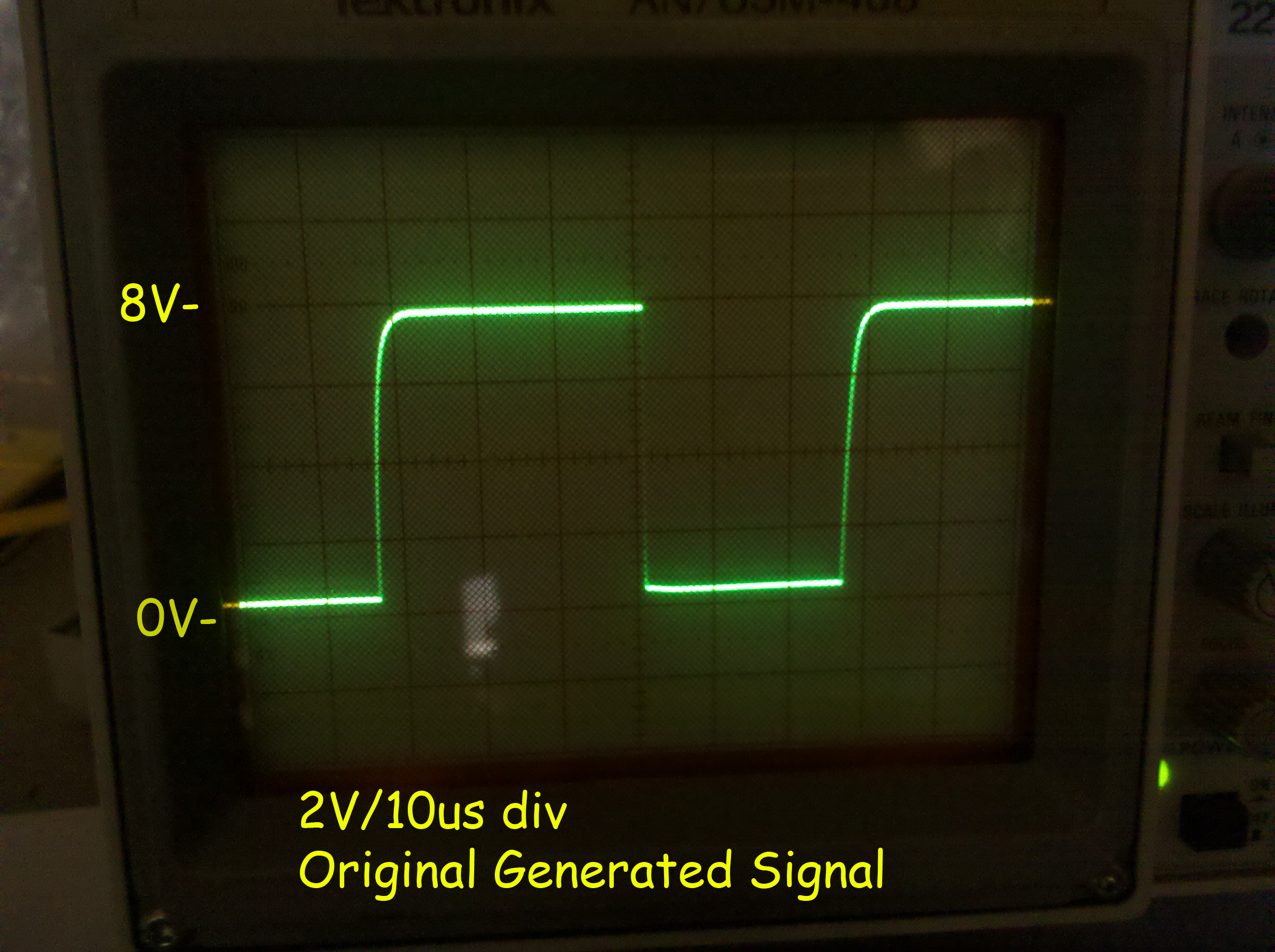
>>>>>>>>>> Okay, I put the standalone LOPT onto my square wave
>>>>>>>>>> generator (unfortunately my generator can only supply
>>>>>>>>>> 30ma) so Im not sure that is enough.
>>>>>>>>>>
>>>>>>>>>> Here is the signal before attaching the LOPT....
>>>>>>>>>> 15KHz 9vP-P
>>>>>>>>>>
>>>>>>>>>> http://gamearchive.askey.org/Video_Games/Manufacturers/Atari/monitors/amplifone/raster/images/generator_output_15k.jpg
>>>>>>>>>>
>>>>>>>>>> Here is the primary with that signal attached...
>>>>>>>>>> secondaries are exactly the same waveform, yet in
>>>>>>>>>> different ratios (and those ratios are not correct)
>>>>>>>>>>
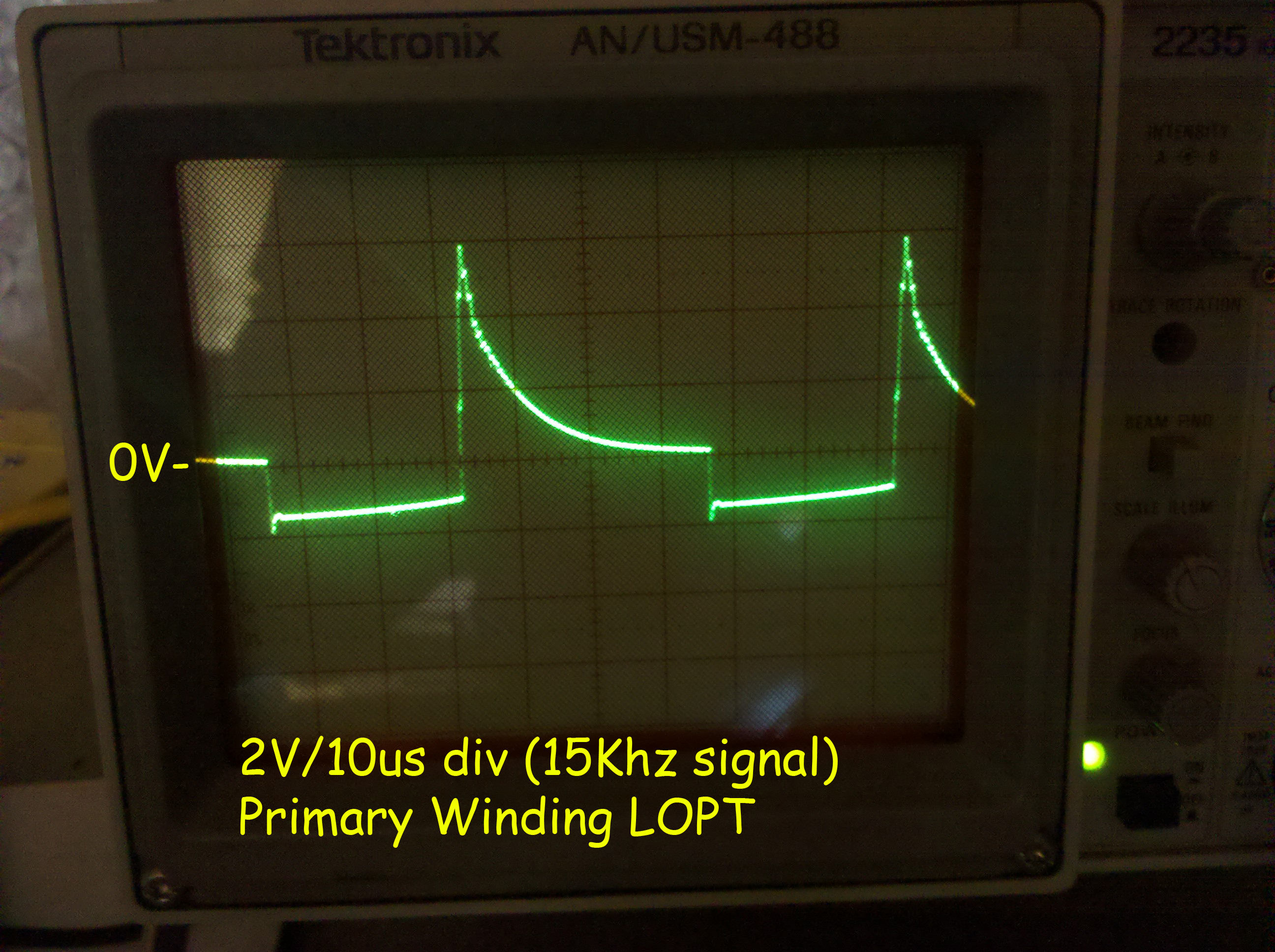
>>>>>>>>>> http://gamearchive.askey.org/Video_Games/Manufacturers/Atari/monitors/amplifone/raster/images/lopt_ringing_15k.jpg
>>>>>>>>>>
>>>>>>>>>> Doesn't look right.
>>>>>>>>>>
>>>>>>>>>> When I read a DC voltage on the Anode cap, I have
>>>>>>>>>> 2.2VDC, pretty low. :-(
>>>>>>>>>>
---------------------------------------------------------------------------
** Unsubscribe, subscribe, or view the archives at http://www.vectorlist.org
** Please direct other questions, comments, or problems to chris@westnet.com
Received on Tue Jan 25 10:48:57 2011
This archive was generated by hypermail 2.1.8 : Mon Jan 31 2011 - 21:50:01 EST